
Reliable Digital Oscilloscope Essentials for Accurate Signal Analysis
2026-07-29
When chasing elusive signal anomalies, the tools you trust define your success. A reliable digital oscilloscope isn’t just a bench instrument—it’s your window into circuit behavior, and getting accurate signal analysis demands more than just bandwidth numbers. From probing techniques to sample rate considerations, every detail matters. At TPS, we understand that precision and repeatability aren’t optional; they’re the foundation of every measurement you make. This post unpacks the essentials that turn raw waveforms into actionable insights, helping you avoid common pitfalls and capture what your signals are really trying to tell you.
Grasping Bandwidth and Sampling Rate Interplay
Think of bandwidth as the gatekeeper deciding which frequencies make it through, while the sampling rate dictates how often we capture snapshots of the signal. If the sampling rate isn't at least double the bandwidth, you end up with aliasing—phantom frequencies that corrupt the original message. In practice, engineers often push the sampling rate a bit higher just to give themselves some breathing room, ensuring real-world filters can do their job without distorting the signal of interest.
The real dance happens when you balance these two parameters in a system. A wider bandwidth lets you see more detail in the time domain, but demands a proportionally higher sampling rate, which in turn eats up processing power and memory. It's not just about following Nyquist to the letter; it's about understanding what you're willing to sacrifice—precision, storage, or speed—and designing accordingly.
And then there's the oversampling trick: by cranking up the sampling rate well beyond the bare minimum, you can spread quantization noise over a larger spectrum, making it easier to filter out. This interplay is what lets modest converters deliver spectacular dynamic range, all while sticking within the bandwidth limits that define your signal's true shape.
Probing Techniques That Preserve Signal Integrity
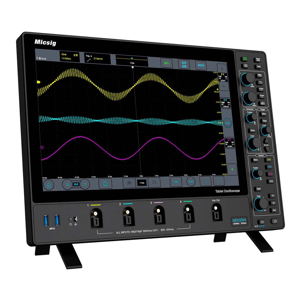
When you're working with high-frequency signals, the way you make physical contact with a circuit can dramatically affect measurement accuracy. Even the most carefully chosen probing point can introduce parasitic capacitance and inductance, causing reflections, ground loops, or outright signal distortion. Instead of treating the probe as an afterthought, consider it an integral part of the system—its input impedance, tip geometry, and grounding scheme all shape the signal before it ever reaches your oscilloscope.
One often-overlooked aspect is the ground lead length. That simple alligator clip dangling from the probe might work fine at low frequencies, but above a few megahertz, the loop area it creates becomes a magnetic antenna, coupling noise into your measurement. Minimizing this loop is crucial, and switching to a spring-loaded ground tip or using a coaxial probe connection can make a night-and-day difference. Additionally, differential probing techniques can suppress common-mode noise and eliminate ground reference issues, particularly in floating or high-side measurements.
Preserving signal integrity also means matching the probe's bandwidth to the signal's rise time and harmonics. A probe with insufficient bandwidth rounds off fast edges, while one with excessive bandwidth may introduce unnecessary noise. Adjusting the probe compensation for flat frequency response, choosing the appropriate attenuation ratio, and even employing resistive-tip probing for high-impedance nodes can prevent common pitfalls. Ultimately, probing is not just about seeing a waveform—it's about seeing the waveform as it truly is, and that demands a deliberate, thoughtful approach to every connection.
Triggering Mechanisms for Isolating Anomalies
Effective anomaly detection systems rely on well-crafted triggers to separate unusual patterns from normal behavior. These triggers can range from simple threshold breaches, where a metric surpasses a predefined boundary, to more nuanced statistical tests that spot deviations in data distributions. The key is to design mechanisms that fire promptly without drowning teams in false alarms, which often means layering multiple conditions or using adaptive baselines that learn from historical trends.
Beyond static rules, modern approaches incorporate behavioral analysis to isolate anomalies dynamically. For instance, a sudden drop in transaction volume might be normal during off-peak hours but suspicious during a weekday rush, so time-aware triggers adjust sensitivity accordingly. Similarly, multi-dimensional checks can scrutinize combinations of metrics—like response time paired with error rates—to catch issues that single-metric alerts would miss. These intelligent triggers help quarantine genuine anomalies while sparing operators from alert fatigue.
Another practical strategy involves feedback loops where operator actions refine the isolation process. When an analyst dismisses a detected anomaly as benign, the system can automatically tune its triggering thresholds or add contextual filters for future occurrences. This human-in-the-loop design ensures the isolation logic stays relevant as environments evolve, bridging the gap between automated precision and real-world expertise.
Memory Depth and Its Impact on Long Capture Analysis
When analyzing long-duration signals, memory depth becomes a critical factor that shapes the entire measurement. It dictates how many sample points can be stored, directly affecting the time window you can capture without compromising on the sampling rate. A deep memory buffer allows the system to maintain high resolution over extended periods, preserving transient events that might otherwise slip between the gaps. Without sufficient depth, you're forced to reduce the sample rate as you stretch the capture window, leading to aliasing and lost details.
In practice, the impact of memory depth extends beyond simple record length. It influences your ability to zoom into specific areas of interest after the acquisition, enabling detailed post-capture analysis. For protocols with sparse bursts or intermittent faults, deep memory ensures you can see both the macro-level timing and the micro-level signal integrity issues without needing to retrigger. This non-invasive insight is crucial when dealing with rare anomalies, as it preserves the full context of the event alongside the fault itself.
However, deeper memory isn't a free lunch. It can slow down waveform update rates and increase processing overhead, so the design of the acquisition system must balance this resource carefully. Modern architectures often segment memory to target only the active portions of a signal, effectively extending the total capture span while maintaining responsiveness. This intelligent management allows engineers to perform long capture analysis efficiently, ensuring that the depth serves the analysis rather than burdening it.
Noise Reduction Strategies for Reliable Measurements
Achieving reliable measurements hinges on effectively taming noise from the very start. One of the most straightforward yet powerful approaches is to pay meticulous attention to cabling and grounding. Twisted-pair wiring, for instance, naturally cancels out electromagnetic interference by ensuring that induced noise appears equally on both conductors, where it can be rejected by differential inputs. Keeping signal wires short, shielded, and well-separated from power lines further prevents capacitive and inductive coupling at the source. It's also worth investing in high-quality connectors and confirming that all ground connections follow a single-point scheme to avoid ground loops, which can introduce subtle but pervasive hum.
Beyond physical setup, the way you process the signal can make all the difference. Averaging multiple samples is a classic digital filtering technique that effectively reduces random noise by the square root of the number of averages, though it comes at the cost of slower response times. For dynamic signals, a low-pass filter with a carefully chosen cutoff frequency can strip away high-frequency hash while preserving the measurement bandwidth you actually care about. In more demanding environments, adaptive filters or lock-in amplifiers can pull coherent signals out of overwhelming background noise by referencing a known frequency. The key is to match the filtering strategy to the nature of both the signal and the interference—there is no universal preset.
A less obvious but equally critical layer of noise reduction lies in component selection and circuit design. Low-noise amplifiers and precision voltage references, though slightly more expensive, dramatically lower the baseline noise floor of an analog front end. Thermal noise in resistors, often overlooked, can be minimized by using lower resistance values and keeping operating temperatures stable. Whenever possible, choosing sensors with inherently high signal-to-noise ratios—like digital-output sensors that perform on-chip conditioning—eliminates entire categories of analog noise before they even reach the measurement system. Combining these hardware choices with the right layout practices, such as keeping analog and digital ground planes separate, creates a robust foundation that software filtering alone can never fully rescue.
Advanced Analysis Tools Beyond Basic Waveform Viewing
Modern oscilloscopes and signal analyzers extend far beyond simple voltage-over-time displays, incorporating a suite of sophisticated tools that transform raw data into actionable insights. These advanced capabilities allow engineers to diagnose intermittent faults, characterize signal integrity, and verify compliance with industry standards—all within a single instrument. By moving past basic waveform viewing, users can isolate glitches, measure tiny timing variations, and visualize frequency components that would otherwise remain hidden.
Key examples include deeply integrated serial protocol decoding for buses like I2C, SPI, and CAN, which overlays decoded packet content directly on the waveform. Real-time eye diagrams offer a rapid view of channel performance, while jitter analysis breaks down timing errors into random and deterministic components. Built-in spectrum analysis and digital filtering let you examine spectral purity or isolate specific frequency bands without needing a dedicated spectrum analyzer. Automated measurement suites and pass/fail mask testing further streamline debugging and production validation, making these instruments indispensable for complex electronic designs.
FAQ
A stable internal clock, low jitter, and a well-shielded front end keep readings consistent over time and across different signal types. Hardware that resists drift and noise allows you to trust the waveform you see on screen without second-guessing.
Sample rate determines how many points the oscilloscope captures per second. If it's too low, fast transients or high-frequency details can be missed or distorted. A good rule of thumb is to sample at least five times faster than the highest frequency component you're trying to observe.
Bandwidth dictates the maximum frequency the scope can measure without significant attenuation. If your signal has faster edges or harmonics beyond the scope's bandwidth, the displayed waveform will be rounded off, hiding important details that might be causing problems.
Look for deep memory to capture long signal records, fast waveform update rates to spot glitches, advanced triggering options to isolate rare events, and a user interface that doesn't get in the way. Solid probes and a responsive display matter more than raw specs on paper.
Start by matching the probe to the signal and compensating it properly. Use the shortest possible ground lead, keep signal paths clean, and set the vertical scale to use as much of the ADC range as possible without clipping. Averaging and filtering can reduce noise, but be careful not to smooth away real anomalies.
Probes aren't just accessories—they load the circuit and shape what the oscilloscope sees. A mismatched or poorly compensated probe introduces capacitance and resonance that distort edges. Active probes or differential probes may be necessary for high-frequency or floating measurements.
Ignoring probe compensation, using ground leads that are too long, relying on automatic measurements without understanding how they're computed, and neglecting to verify trigger stability. Also, trusting a scope's default settings without checking sample rate or memory depth can lead to misleading results.
Conclusion
Achieving trustworthy signal analysis starts with a firm grasp of bandwidth and sampling rate interplay. An oscilloscope's bandwidth must exceed the highest frequency of interest, yet sampling rate is equally critical—Nyquist alone isn't enough; real-world signals demand oversampling to capture fast edges and subtle glitches. Pairing this with probing techniques that preserve signal integrity is non-negotiable. Even a premium scope can be undermined by long ground leads or mismatched probe capacitance, which distort rise times and introduce ringing. Meanwhile, advanced triggering mechanisms turn the instrument from a passive viewer into an active anomaly hunter. Pulse-width, runt, and logic-qualified triggers isolate infrequent faults buried in repetitive traffic, reducing debug time dramatically.
Beyond capture, memory depth dictates how long you can maintain high resolution during extended acquisitions. Long records let you zoom into microseconds of interest after a capture without sacrificing sample rate, vital for hunting intermittent dropouts or serial protocol decode. Noise reduction strategies—ranging from bandwidth limiting and averaging to high-resolution acquisition modes—clean up low-level measurements on millivolt signals. Finally, moving past basic waveform viewing, built-in measurement automation, FFT analysis, and mask testing push the scope into a complete analysis platform. When these elements are carefully calibrated to the task, the digital oscilloscope evolves from a simple display to a reliable measurement engine that exposes signal truths with clarity and confidence.
Contact Us
Contact Person: Lily
Email: [email protected]
Tel/WhatsApp: +49 (0) 2161 49526-0
Website: https://tps-elektronik.com/en/